MAE101
Engineering Lab I
Content
Lab Report
It is important for students to communicate his or her knowledge of the subject with well-written individual lab report that are decent and that accurately explain the efforts, hypthesis or concise theoretical background of the the topic under inverstigation, observations and discussion of the results. it is imperative for the student to keep in mind that instructor may not be the only reader of the report and to write in a clear fashion such that other people who are unfamiliar with the subject matter can read and understand the material presented. Desirably the narration sould be free of any commitment to any person(s), that is refrain from the use of pronouns such as I, We, Our, Us, etc.
To convey understanding, the organization of the lab report should lead to a deft arrangment of information including data, graphs, and pertinent answes to such questions posed by the experiments.
The preferred lab report format is typewritten, double-space. thus for this course the guideline for an acceptable lab report format is outlined in the following example Lab Report Ouline
Also a Lab report template is available here Lab Report Template
Bridge Design Module
In This Module you will study the behavior of material, structural members and equilibrium.
Lab Experiments:
Student are required to submit an individual lab report for the each experiment. PDFs are the preferred format since PDFs can be uploaded to Blackboard.
- Experiment 1 : Fatigue Failure
- Experiment 2 & 3 : Tension & Compression Test
- Experiment 4 & 5 : Bending of Beam & Moments of Forces
- Experiment 6 & 7 : Internal Forces in Truss Members & End Reaction of a loaded Beam
Student are required to submit an individual lab report for each experiment. PDFs are the preferred format since PDFs can be uploaded to Blackboard. Also make sure you write a separate lab report for each experiment.
Experiments Data and Handouts:
| Experiment | Manual | Data | Resources |
|---|---|---|---|
| Fatigue Failure | Handout | Get Data | Video1, video2, video3, video4 |
| Tension Test | Handout | Get Data | Demo |
| Compression Test | Handout | Get Data | Eulers Equation – Backling Example |
| Bending of Beam | Handout | Get Data | Demo - Virtual lab Demo–Free Beam Calculator |
| Moments of Forces | Handout | Get Data | Using Interactive |
| End Reaction of a Loaded Beam | Handout | Get Data | Beam Calculator |
| Interenal Forces in Truss Members | Handout | Get Data | Setup and Instruction Manual- Truss Simulator - Equilibrium |
Values of modulus of elasticity:
| Material | E value in [Pa] | E value in [psi] |
|---|---|---|
| Rubber | $$1.72\times 10^6$$ | $$250$$ |
| Aluminum | $$70\times 10^9$$ | $$10\times 10^6$$ |
| Wood | $$15\times 10^9$$ | $$2\times 10^6$$ |
| Ruler | $$2.8\times 10^9$$ | $$400\times 10^3$$ |
Project: Design & Analysis of a Warren Truss Bridge
The last section demonstrated the use of powerful tool for analyzing civil engineering structures where the program was used to perform static analysis of truss. The SAP2000 program is also capable of analyzing frames plates and shell for static as well as dynamic loads. In this section, its application will be extended to the analysis of a simple truss bridge.
SAP2000 Software
Please follow these steps to download, install, and activate your software.
- Download Get SAP2000 Student Version .
- Run the installation.
- After installation is done use the following zip file to activate the software: unzip and extract the license into the SAP2000 23 ED folder (where the executable is located). Overwrite the existing license file with the new one.
SAP2000 programs cannot be run directly within the Mac operating system. However, if Windows operating system is virtualized on the Mac machine (via virtualization platforms such as Parallels or VirtualBox) then SAP2000 programs can be run within such virtualized Windows operating system.
Introductory Tutorial for SAP2000
The manual provided bellow will introduces you to SAP2000. The step-by-step instructions guide you through development of your first model. The intent is to demonstrate the fundamentals and to show how quickly and easily a model can be created using the program. Completing the tutorial will give you hands-on experience working with SAP2000, which for most people is the quickest way to become familiar with the program.
Download SAP2000 Tutorial First Problem SolutionThe pdf tutorials were created using SAP2020 v17. In the New SAP2020 v20 there are some small changes related to how live load is applied. Please follow the animation below to see how to define the loads on SAP2020 v20.
Design and Analysis Of a WARREN Truss Bridge
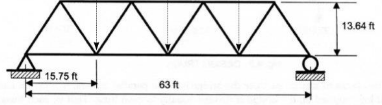
Perform the structural analysis of a steel truss bridge that spans a total distance of 63 ft. The truss bridge consists of two parallel trusses and the truss configuration is given in the figure below. The lower chords of the trusses support the roadway which in turn carries the car and truck traffic. The object of this analysis is to calculate the internal forces in each member of the bridge under the effect of the weight of the bridge and roadway (the dead load) and the weight of the vehicles (the live loads) that are likely to cross the bridge. It is here in assumed that the bridge carries two lanes of vehicle traffic. Make a first estimate of the internal forces in each truss member under regular truck traffic. The analysis must be performed using the SAP2000 package. Use the simplifying assumptions given below to analyze the four-bay Warren truss bridge shown in Fig 1.
Bridge Preliminary design On SAP2000
- WARREN Truss bridge step by step design instructions Download pdf file
- Watch Demo video here
Similary follow the animation below to see how to define the loads on SAP2020 v20.
Bridge Analysis, and Assessement of Results
STEP 1: Calculate the areas required for each member
Use MS-Excel to calculate the areas required for each member to carry the force produced by different loading condition considered. Recall that the analysis of the truss bridge was performed by assuming that each member had an area equal to 20in^2. To find the area required for each member to support the loading conditions, we assumed that A36 structural steel was used with a design safety factor of 1.5. the maximum possible stress is 36,000 psi for A36 steel. Therefore the allowable stress is obtained as :
$$\sigma_{all} = \frac{\sigma_{max}}{S.F} = \frac{36,000 psi}{1.5} = 24,000 psi$$
if the force in a member is given as F and the area is given as A, the stress in the member is $${{{\sigma}}} = \frac{F}{A}$$
if the stress is set at a value equal to the allowable stress, The minimum required area for the steel member is solve as
$$A_{min} = \frac{F}{{\sigma}_{all}}$$
As a first step in the design process. follow the summary table below:
| Member Number | Combination Force (DSTL4) | $$A_{min} = \frac{Force}{{\sigma}_{all}}$$ | $$ A_{required} = A_{min} + margin$$ |
|---|---|---|---|
| 1 | |||
| 2 | |||
| … |
$$DSTL4 = (All\space Live\space Loads) + (Dead\space Loads)$$
Note : the margin is an estimated number that needs to be added in order to find the final area that must be used for each member, and that is the largest area obtained for that member for the different loading conditions considered.
STEP 2: Assign the new required areas to the bridge steel members
- Check the W-Beams - American Wide Flange Beams or S-Beams and select the proper cross section area (e.g. W10x68 for 20in^2) calculated in the previous step.
- In SAP2000 select a member that you want to change the cross section then follow step 3 in the tutorial to assign it.
- Check the safety of a design again and make sure your member is optimum in terms of cost and not overstressed (green Color)
The following video demonstrate how to assign a cross section and check the safety of design.
STEP 3: Cost analysis
After finding the area required for each member, use this excel file template to calculate the volume V of each member. the volume is given by :
$$V = A.L$$
Where A is cross sectional area of the member and L is the length of member. After finding the volume calculate the weight of each element using the specific weigth of steel.
- Steel cost $560 per ton
- Concrete cost $50 per cubic yard
- Calculate only the material cost for the steel members and roadway (neglect connections and Labor costs)
Need help? join the slack channel to request support
Robot Design Module
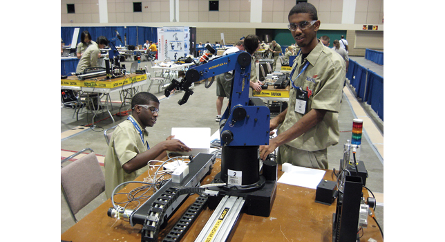
Robotics and Automation Project is an engaging simulation of the industrial automated manufacturing process. Teams of two students layout and program a robotic production system as a solution to the project scenario.
For this project students will use The ScorBot ER-4U robot arm 3D simulation software that simulate the same Robot arm we have in our enineering Lab at LaGuardia Community Collge. The robot’s speed and repeatability make it highly suited for both stand-alone operations and integrated use in automated workcell applications such as robotic welding, machine vision, CNC machine tending and other FMS operations The robot is supported by ScorBase robotics programming and control software. The software provides dynamic simulation of the robot and workcell devices during position teaching and program execution. The robot is designed to enable observation of its working mechanical parts while ensuring a safe environment for students.
Example Applications
- ER 4U with Machine Tending (Milling/Turning/Laser Engraver)
- ER 4U with SkillsUSA materials handling package (RAT – Robotic Automation Technology)
- ER 4U with ASRS (Automated Storage and Retrieval System)
- ER 4U with machine vision system from Cognex for Quality Control
Student Activities
The robot Design Module activities and ER-4U simulation sotftware tutorial will be accessible from the LearnMate platform. Please follow below steps to get access to course content:
- Step 1 Creating an Account : When accessing the site for the first time, you need to create an account with your profile information and a password.
- Step 2 Logging In Before you can login, you must activate your account with the link sent to your email address. If you did not receive this email, please check your junk/spam folder.
- Step 3 Join your course: After logging in click Fundamentals of Robotics for SCORBOT-ER4u course to join. You’ll be asked for a course enrolment key, Enter the enrollment key supplied by your instrucor.
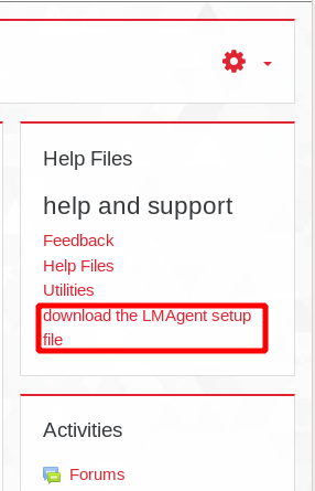
Step 4 Installing Required Utilities :
- LM Agent Software : The LM Agent enables students to lincense and operate the RobotCell software. The required simulation and control software can be launched and controlled directly from the LearnMate environment using the LM Agent. The LM Agent, which utilizes ActiveX technology, runs in the background until required by links in the modules.
- Download ER-4U RobotCell simulation software From Here
- LM Agent Software : The LM Agent enables students to lincense and operate the RobotCell software. The required simulation and control software can be launched and controlled directly from the LearnMate environment using the LM Agent. The LM Agent, which utilizes ActiveX technology, runs in the background until required by links in the modules.
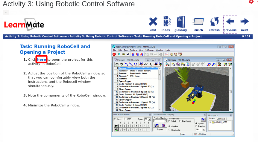
In order to license and use the RobotCell Software, RoboCell needs to be launched from the course content. You don’t need to remain logged into the content or even the site, but you must launch the software from one of the many links found within the course activity. Once that’s done, this process temporarily licenses the software for 3-4 hours, and at that point LearnMate can be exited, minimized, etc. When the temporary license expires, you can log back into the content, click another launch link again to re-apply the license and they’re good to go for another 3-4 hours.
To launch the software go to activity 3 and navigate to Running RoboCell and Opening a Project (9/51) in the content click the link where it says “Click here to open the project for this activity in RoboCell.” the software will launch without any licensing request.
More details in this short manual